 Air Filter and HVAC Service Indicators and Gauges
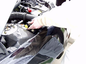
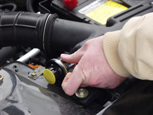
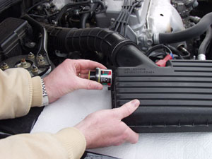
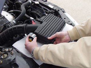
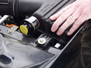
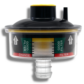
- To determine if the Filter Minder® is working properly, if the window on a single position service indicator is showing red, or the position indicator on a graduated service indicator is showing in the window, reset the service indicator by pushing at the end of the indicator. If it resets to zero, the service indicator is operating properly.
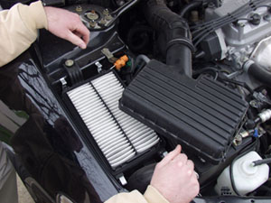
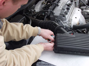
- Remove the service indicator.
- Pull a vacuum on the service indicator until the position indicator reaches red zone. If the position indicator does not lock in the red zone, replace the service indicator. Push the reset at the end of the service indicator to reset to zero. If it does not reset, replace the service indicator. Again, pull a vacuum on the service indicator until it locks in the red zone.
- Re-install the service indicator.
- Push the reset at the end of the service indicator. If it resets to zero, the service indicator and fitting assembly is working properly.
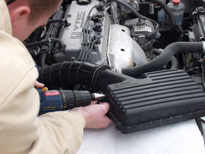
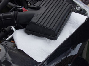
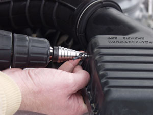
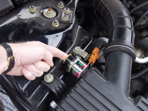
- If the position indicator fails to reset fully to zero, check the air cleaner fitting, as the safety filter in the fitting may be plugged. If plugged, replace the fitting. Replacement fittings with safety filters are available from Filter Minder®. Some fittings are welded to the air cleaner, and cannot be removed. In this case, it will be necessary to drill a hole through the fitting, and add a new adapter fitting with safety filter. Be sure to collect the metal shavings to prevent them from getting into the air induction system. Note: Some systems use rubber grommet mount service indicators, which do not utilize a fitting.
Air Filter Switch Service Indicators
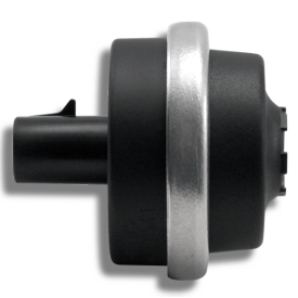
- Check the mechanical operation of the Filter Minder® by following the above instructions for service indicators and gauges.
- To check the operation of the switch, pull a vacuum on the Filter Minder® until the position indicator locks in the red zone. The warning light in the dash should illuminate.
- If the warning light fails to illuminate, proceed in checking proper operation of the switch, wiring, and light bulb per normal electrical maintenance procedures.
- Switch Indicators are available in normally open or normally closed switch designs. See label for switch details.
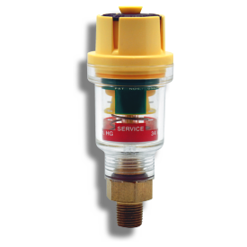
Fuel Filter Service Indicator
- To determine if the Fuel Filter Minder® is working properly, removal of the service indicator is usually not recommended. It can be checked if there is some fuel filter restriction, and the position indicator is showing in the window of the service indicator. Push the reset at the end of the service indicator so that the yellow position indicator returns to zero. Then operate the engine at high idle, and the position indicator should move and lock in the same position. Note: A road test may be necessary to duplicate the reading.
- Check for fuel leakage from the service indicator and fitting. If leaking, replace the indicator and fitting assembly. Note: The fuel filter service indicator is supplied complete with a new fitting that has been assembled by the manufacturer. Do not install a new service indicator to an old fitting.
- If the position indicator is not showing in the clear window, it is possible that there is not enough fuel filter restriction for the service indicator to read. To determine if it is working properly, remove the complete Fuel Filter Minder® assembly including fitting from the fuel system.
- Pull a vacuum on the service indicator until the position indicator reaches the red zone.
- If the position indicator locks in the red zone, it is working properly. If not, replace the service indicator and fitting assembly.
- Re-install the service indicator and fitting assembly, and push the reset at the end of the service indicator.
- Always install a new fuel filter service indicator and fitting complete. The Fuel Filter Minder® and fitting are assembled to the correct specifications at the time of manufacture.